CT of Fuse failure mechanisms
Introduction
Fuses are widely used in electronic systems to protect circuits from damage caused by short circuits or other fault conditions. During a fault, excessive current can flow through the circuit, potentially damaging electronic components. A fuse typically consists of a thin conductive wire enclosed within an insulating protective housing. Understanding the fuse failure mechanism is essential for designing devices that reliably operate and rupture at their specified current rating.
As most fuses are opaque and cannot be disassembled without altering their internal structure, X-ray computed tomography (CT) scanning was used to investigate the failure mode. CT scanning involves acquiring hundreds of X-ray radiographs while the sample is rotated through 360°. These radiographs are then reconstructed into a three-dimensional model for detailed visualisation and analysis.
Experimental
To look inside the fuse, a Nikon XT H 160i CT scanner was used to scan around the fuse using 100kV X-rays, 200uA beam current, 0.25mm copper filter was used to prevent overexposure of the X-ray detector and provides good contrast between elements inside the sample. Due to the systems cone shaped beam the scan geometry was configured to capture the entire fuse within the field of view, resulting in a reconstructed voxel size of 20 μm (38 mm field of view).
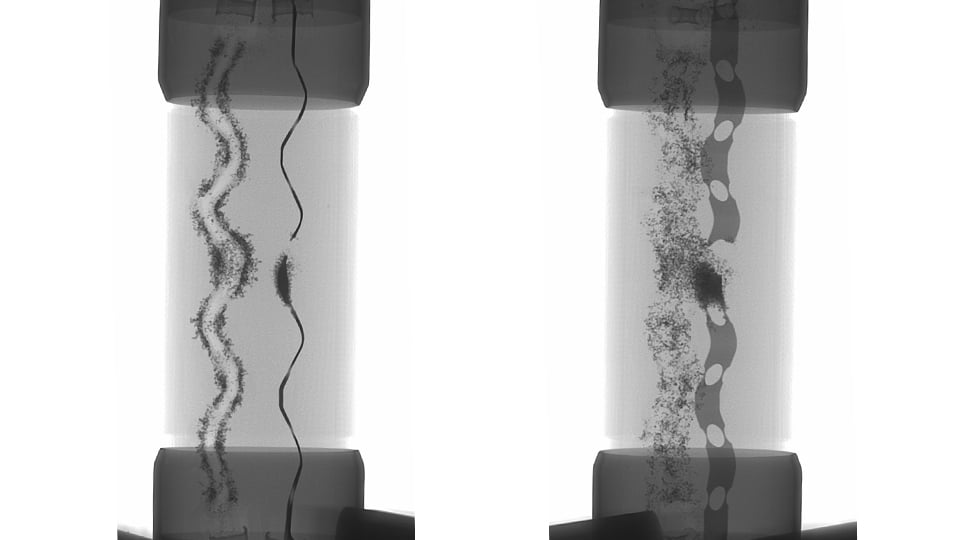
Fig 1: X-ray radiographs of the fuse from side at 90° and 45° from the side view.
Results
 Fig 2: AI segmented slice with the fuse and metal casing in orange & insulation material in green.
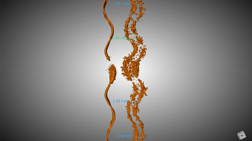
Fig 3: Segmented fuse with annotated edge to edge distances of the failed component.
Summary
Acknowledgement
Melvin Chan